
Plant and process capability
From an optical surface measured in fractions of a wavelength to a press stroke measured in tonnes.
Below is the working envelope of every process group we run — the sizes, tolerances and materials we hold in production, with the equipment behind them named so you can judge the claim.
Precision machining
- Five-axis simultaneous milling
- DMG Mori DMU and Mazak Variaxis centres with thermal compensation, holding ±0.002 mm on parts up to 1500 mm across.
- Turn-mill and Swiss turning
- Bar capacity 3–120 mm, live tooling and sub-spindle transfer for complete parts off one setup.
- Wire and sinker EDM
- Down to ±0.001 mm on hardened die sets, micro-fluidic channels and internal corners a cutter cannot reach.
- Jig grinding and lapping
- Bore position accuracy to 2 µm and Ra 0.05 µm on sealing and bearing faces.
Optical fabrication & assembly
- Deterministic polishing
- Magnetorheological finishing and CNC polishing to λ/20 surface figure, 10/5 scratch–dig, on apertures from 3 to 300 mm.
- Aspheric generation
- Single-point diamond turning for IR materials and precision glass moulding for volume visible asphere production.
- Thin-film coating
- Ion-assisted deposition for AR, HR, dichroic and beamsplitter stacks, with witness samples retained per run.
- Cleanroom opto-mechanical assembly
- ISO 7 bonding, active alignment, nitrogen purge and sealing to IP67, verified by helium leak test.
Forming, stamping & casting
- Progressive and transfer stamping
- 200 t to 1500 t press lines, blank thickness 0.5–8.0 mm in grades up to DP980 advanced high-strength steel.
- High-pressure die casting
- 280 t to 1250 t machines in ADC12 and A380, with vacuum assist where porosity limits the application.
- Aluminium extrusion
- Circumscribing circle to 320 mm, custom dies cut in-house, tolerances to EN 12020-2.
- Injection moulding
- 50 t to 1300 t, engineering resins including PA66-GF, PPS, PEEK and optical-grade PMMA and COP.
Materials & chemical processing
- Isostatic graphite & purification
- Cold isostatic pressing to 1200 × 2000 mm blocks, halogen purification below 5 ppm ash, SiC and pyrolytic coating.
- Carbon–carbon composites
- Chemical vapour infiltration for furnace fixtures and thermal shields that survive repeated 2000 °C cycling.
- Batch chemical synthesis & blending
- Glass-lined and stainless reactors from 0.2 to 25 m³, with closed-loop effluent treatment under ISO 14001.
- Heat treatment & surface engineering
- Vacuum hardening, nitriding, hard anodising, electroless nickel, PVD and zinc-nickel plating.
Insulation coating & converting
- Laminating and coating lines
- Adhesive coating and nip lamination to 1300 mm web width, with a continuous beta gauge holding thickness inside five per cent of nominal.
- Slitting and die-cutting
- Slit widths from ten millimetres upward and rotary die-cut slot liners, cuffed and formed to the lamination drawing.
- Varnish and resin impregnation
- Dip-and-bake and trickle impregnation with solvent-free resin, cure schedules validated on your own winding before release.
- Dielectric testing
- AC breakdown, thermal endurance to IEC 60216 and flammability witness samples pulled from every production lot.
Fermentation & downstream
- Corn wet milling
- Steeping, germ and fibre separation and starch washing, feeding liquefaction and saccharification to a glucose stream at DE 96.
- Fermentation trains
- Seed and main fermenters to 500 m³, sterile air, cascade control on dissolved oxygen, temperature and pH, with off-gas analysis on every batch.
- Separation and crystallisation
- Membrane filtration, ion exchange, evaporative crystallisation and centrifugal separation, with mother liquor recycled rather than discharged.
- Drying, milling and packing
- Fluid-bed drying to a controlled particle distribution, metal detection and check-weighing before bagging into 25 kg or one-tonne packs.
Fabrication & joining
- Sheet metal and enclosure fabrication
- Fibre laser cutting to 20 mm, CNC bending with angle compensation, robotic deburring.
- Certified welding
- MIG, TIG, laser and friction-stir welding to ISO 3834-2, with qualified procedures and welder records on file.
- Busbar and conductor forming
- Copper and aluminium lamination, punching, bending and tin plating for switchgear and battery interconnects.
Test & validation
- Dimensional metrology
- Zeiss bridge CMMs in a 20 ± 1 °C room, optical comparators and CT scanning for internal features.
- Optical metrology
- Zygo interferometry, spectrophotometry across 200–2500 nm and MTF benches for assembled heads.
- Environmental and life testing
- Thermal shock, damp heat, salt spray to 1000 h, vibration and IP ingress chambers.
- Material analysis
- Optical emission spectrometry, XRF for RoHS screening, metallography and ultrasonic flaw detection.
What we will sign for
Sustained capability, not a lucky first article.
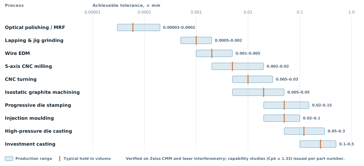
The band is the range our sites hold across a production run. The marker is the figure that goes into a contract, backed by a capability study on your part number before the first serial shipment.
Worked example
A sealed sensor head, built as one part number.
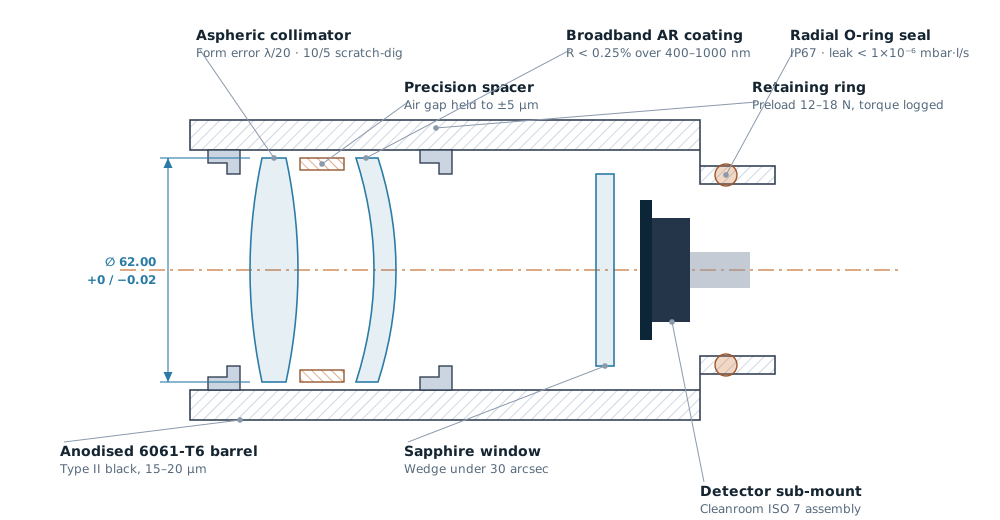
This is the kind of assembly that usually needs four suppliers: a lens polisher, a coating house, a machine shop for the barrel and a cleanroom for the build. All four operations are ours, in one building, so we quote it as a single line item, inspect it as one assembly and warrant it as one product.
- Tolerance budget agreed before the first surface is cut
- Interferogram and coating scan retained per serial number
- Helium leak test on every sealed unit, not a sample
Equipment matrix and working envelopes
The machines listed are the largest or most capable of their type in the group. Capacity below these limits exists in more than one factory, which is what lets us qualify a second line for a part without leaving the company.
| Process | Machine | Working envelope | Held tolerance | Runs at |
|---|---|---|---|---|
| Five-axis milling | DMG Mori DMU 210P, Mazak Variaxis i-800 | 1500 × 800 × 700 mm | ±0.002 mm | Suzhou, Monterrey, Rayong |
| Swiss turning | Citizen L32, Tsugami B0326 | Ø3–32 mm bar | ±0.005 mm | Suzhou, Bac Ninh |
| Wire EDM | Sodick AL600G | 600 × 400 × 350 mm | ±0.001 mm | Suzhou, Monterrey |
| Optical polishing | QED MRF Q-flex 300, Satisloh CNC | Ø3–300 mm | λ/20 PV | Penang, Suzhou |
| Diamond turning | Nanotech 450UPL | Ø450 mm | Ra 3 nm | Penang |
| Thin-film coating | Bühler SYRUSpro 1110 IAD | 1100 mm chamber | R < 0.25% | Penang, Suzhou |
| Progressive stamping | 1500 t hydraulic, 400 t servo lines | 2500 × 1200 mm bed | ±0.05 mm | Monterrey, Ningbo |
| Die casting | Bühler Carat 1250 t, vacuum assist | 18 kg shot weight | ±0.12 mm | Suzhou, Monterrey |
| Injection moulding | Engel duo 1300 t, Fanuc Roboshot | 4200 cm³ shot | ±0.05 mm | Bac Ninh, Dongguan |
| Aluminium extrusion | 2750 t press | 320 mm circle | EN 12020-2 | Ningbo |
| Graphite purification | Halogen vacuum furnace | 1200 × 2000 mm block | < 5 ppm ash | Ningbo, Rayong |
| Coordinate metrology | Zeiss Prismo Navigator | 1200 × 2400 × 1000 mm | MPE 0.9 µm | Every plant |
Before steel is cut
Simulation is cheaper than a second tool.
Every programme is modelled before tooling is released. The output is not a certificate — it is a list of the specific features that will cost you money and what changing them would save. You decide which to accept.
Optical modelling
Zemax OpticStudio tolerance analysis showing which surfaces actually drive the performance budget, and which can be loosened.
Structural analysis
ANSYS static, modal and thermal studies on housings, brackets and battery trays before the die is designed.
Flow and fill simulation
Moldflow and MAGMA studies predicting weld lines, porosity and warpage, with gate positions proposed and costed.
Forming simulation
AutoForm springback and thinning prediction on high-strength steel and aluminium stampings.
Prototype routes and lead times
| Route | Typical lead time | Best for |
|---|---|---|
| CNC prototype | 7–12 days | Fit and function, 1–50 pieces |
| Soft tool moulding | 18–25 days | Material validation, 100–3,000 pieces |
| Prototype optics | 15–30 days | Single-point turned or polished singlets |
| Production tooling | 4–10 weeks | Serial launch with PPAP submission |